Kategorier
- Alarmer AIA anlæg
- Aflytning
- Aktiv IR til hegn sikring
- ANPR & LPR system
- Bak/Auto Kamera
- Body worn camera
- Brandskabe
- Dash / Bil kamera
- Diims
- Diverse
- Dokumenter
- Informationer
- GPS Sporing
- Auto tracking PTZ camera
- Face detection
- Fish Eye kamera
- AHD (Analog High Definition)
- 3 in 1 Hybrid camera
- 4 in1 Hybrid camera
- 4K opløsning
- H.265 system
- HD video transmission standard HDCVI
- Dahua 2MP Starlight HDCVI
- Dahua HDCVI recorder XVR - HCVR
- Dahua HDCVI 4.0MP
- Dahua HDCVI 5MP
- Dahua HDCVI 8.0MP 4K
- HD-TVI Technology
- Hegn sikring
- Industri kamera
- Intercom systemer
-
Kamera IP/Netværk
- 1 Mega Pixel IP kamera
- 1.3 Mega Pixel IP kamera
- 2 Mega Pixel IP kamera
- 3 Mega Pixel IP kamera
- 4 Mega Pixel IP kamera
- 5 Mega Pixel IP kamera
- 6 Mega Pixel IP kamera
- 8 Mega Pixel IP kamera
- 12 Mega Pixel IP kamera
- Antenner & repeater
- IP kamera
- NAS/NVR
- Network Server / Adapter
- POE kamera
- Powerline
- Router
- Switch
- Tilbehør kabler mm
- Starlight Ultra Low Illumination Megapixel IP Camera
- Fiber optisk
- Kamera med solceller
- Kamera Katalog
- Kamera Spion
- Kamera Tilbehør
- Kamera Trådløst
- Kommende modeller
- Marine & explosionssikre kamera
-
Mærker
- acer
- AI teknologi
- ASUS
- AXIS
- BenQ
- Bosch Security
- BlackVue
- Cisco Linksys
- D-Link
-
Dahua
- Dahua Informationer
- Dahua IMOU
- Dahua consumer Lechange
- Dahua HDCVI kategori
- Dahua diverse
- Dahua beslag
- Dahua recorder
- Dahua XVR
- Dahua Access ANPR Camera
- Dahua LPR og Parking camera
- Dahua epoe
- Dahua 2 MP IP Camera
- Dahua 3 MP IP kamera
- Dahua 4Mp Ip kamera
- Dahua 5MP IP kamera
- Dahua 6 MP IP Camera
- Dahua 8MP IP kamera
- Dahua 12 MP IP Camera
- Dahua 4K Ultra Solution
- Dahua PTZ kamera
- Dahua fisheye camera
- Dahua Thermal serie
- dahua wifi
- Dahua Explosion-proof
- Dahua rustfri kamera
- Dahua dørtelefon / Intercom
- dji droner
- Enster
- ENXUN
- flir
- Foscam
- GeoVision
- GPA
- GPA MegaPixel IP kamera
-
Hanwha Techwin Europe Limited
- Hanwha - Wisenet analog kamera
- Hanwha - Wisenet DVR
- Hanwha Lens Module
- Hanwha - Wisenet 2MP kamera
- Hanwha - Wisenet 4MP kamera
- Hanwha - Wisenet 5MP kamera
- Hanwha - Wisenet 6MP kamera
- Hanwha - Wisenet 12MP kamera
- Hanwha - Wisenet PTZ kamera
- Hanwha - Wisenet NVR
- Hanwha - Wisenet beslag
- Hanwha - Wisenet diverse
- Hanwha - Wisenet Licens
- HDCVI
- HD-TVI Technology
- Hikvision
- HP
- Jablocon
- Kingston Technology
- König
- Longse
- Milesight lagersalg
- Monacor
- Mytech
- NATURE
- NUUO
- OEM leverandør
- OPTEX
- QNAP
- Panasonic CMOS sensor
- Parrot droner
- PHILIPS
- pioneer
- Raytec
- Redwall
- Samsung
- Santos
- Seagate
- SelectaDNA
- Sony IMX291 Starvis sensor
- Synology
- TP-Link
- Transcend
- Trivision
- Ubiquiti
- Videotec
- Visonic
- Vivotek
- Western Digital
- Wisenet - Samsung
- Xexun GPS
- ZyZEL
- 70mai Dash Cam
- Mærkning DNA
- Thermal Imaging kamera
- Montering & Service
- Optagere DVR
- NVR optagere
- Ordre & Tilbud
- Outlet
- Pakker
- POE
- R/C kamera - sender - udstyr
- Smart Home
- Sports Kamera
- Video
- Video Encoders
- Våbenskabe
- WiFi kamera
- Demo varer - SPAR KR.
- Returvarer - nedsat 50%

Søg

20 andre varer i samme kategori:
Forrige
Næste
-

GSM Alert...
Vis
-

Outdoor...
Vis
-

GSM Remote...
Vis
-

Lampe med...
Vis
-

Lampe med...
Vis
-

REDWALL...
Vis
-

REDWALL...
Vis
-

REDWALL...
Vis
-

OPTEX -...
Vis
-

OPTEX -...
Vis
-

OPTEX - PIR...
Vis
-

TV-simulator...
Vis
-

König - Full...
Vis
-

VIGTIGT for...
Vis
-

NiveauVagt...
Vis
-

NYT SIMKORT...
Vis
-

Xiaomi...
Vis
-

130db...
Vis
-

Nedis®-nøgle...
Vis
-

Pro Radar...
Vis
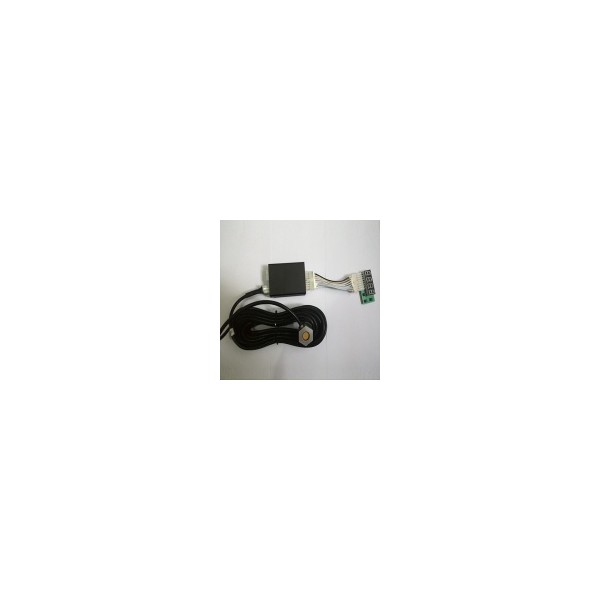
Ultrasonic fuel level sensor
ESMUS01
1.Overview
With non-contact measurement ultrasonic transducer technology, widely used in detecting displacement, thickness, distance, fuel level, material level, and transparency, suitable for measuring of liquid level, gaseous media and volume.
2.Feature
1)ultrasonic signal,Baud Rate,measuring range,Algorithm mode can manually adjust
2)Power supply analog output:0.1-3V;digital voltage:RS232
3.Main Technical data
Name
Value
Measuring range 3.5~200m
Working voltage 7~38V
Maximum Load Current 3mA
Working Current 60mA (12V)
Working temperature -40~+80 celsius
Interface
One way analog output0.1~3.0V,RS232
ultrasonic probe protection Level
IP66 Master control box protection level
IP61
4.Pack detail
1)Master Box:1PC
2)Ultrasonic probe cable:9m
3)Power, serial, voltage signal output harness
4)Glue,couplant,sandpaper.etc
5.Setting and display
1)interface(Output level value)
- Interface: This device provides RS232 data port, analog output voltage
- RS232 serial port: The default is 9600 baud, level sensors in real time values for each
measured pass 10S (in units of 0.1mm). The baud rate can be modified according to the user
needs to be done, the time interval data transmission
-Voltage sampling port:The output voltage of the voltage output from the current level value and
the size of the set range determined.
2)Digital display content
-Liquid level value:Shown as picture 2,current level value is 242.0mm
-Signal Value:as shown in picture 3,the value is 3,max9,due to the specificity ofultrasonic,Signal value is not the bigger the better, the control signal is 2 or 3 when the tank is full of oil.
3)Parameter setting
A.Setting the signal valuewhen the poor signal (too big or too small) touch of a button press "1" key for 8 seconds or more to enter the signal reception sensitivity settings, press the "2" key signal sensitivity increases, press "3 "key signal sensitivity decreases, press" 1 "key for 8 seconds or more, save sensitivity digital interface jump back to Figures 2 and 3 switching state.Without having to power transmission, can modify the signal sensitivity, Sensitivity defaults to 20
B.Setting the device full measuring Shown in Figure 5, when the modified full-scale equipment, while long press touch of a button "1 and 2" button for 8 seconds or more full-scale settings, press the "2" key full-scale increases, press the "3" key full scale decreases, press "1" key for 8 seconds or more, save full-scale sensitivity digital interface jumps back to Figures 2 and 3 switching state. Equipment needed to re-power program will be executed.Full measuring range defaults to 80 cm.
C.Setting the baud rateAs shown in Figure 6, when devices change the baud rate, while long press touch of a button, "2 and 3" button for 8 seconds or more full-scale settings, press the "2" key to increase the baud rate, press "3 "key to reduce the baud rate, press" 1 "key for 8seconds or more, save baud rate, the digital interface jump back to Figures 2 and 3 switching state. Equipment needed to re-power program will be executed. The default baud rate is 96 * 100= 9600
D.Set device algorithm execution(Not suggest to modify)Shown in Figure 7, when the modified algorithm devices while long press touch of a button, "1, 2 and 3" key 8 seconds algorithm settings, saving algorithm mode, the digital interface jump back to Figures 2 and 3 switching state. Equipment needed to re-power, the program will execute the new settings. Algorithm defaults to "1" mode.
E.Wiring
- Power cord: Coarse red (car battery positive), bold black(Car Ground).
-Signal line: yellow (connected user devices (GPS) of the RS232 RX line), blue (user equipment
connected to the RS232 TX line), green (user equipment connected to a voltage sampling port),
thin black (user equipment to).
-Ultrasonic probe line: 9 meters long, plug end of the terminal 6 holes
6.Installation guide
A.Probe line extension cable installation
- Extension cord should outsource a protective cover, such as heat-shrink tubing. When the
vehicle wiring along the skeleton or the location of the original wiring go, extension cords and
vehicle heating parts, components should be at least 20 cm distance.
- Extension cord can be lengthened if necessary, the total length of the probe line does not allow
more than 15 meters.
-Power red wire car battery positive and black wire to the car's Ground
- ESMUS01 ultrasonic fuel
ESMUS01 ultrasonic fuel level sensor install instruction